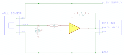
Hall Probe Circuit Diagram
Probe calibration tps magnet cryogenic Passive schematic hiclipart Transducer funktion hallsensor efek prinsip principals a3144 aufgebaut transduser wiring electrical frage schematische rpm explanation
Group3 Hall Probes and Closed Loop Magnetic Control
Linear hall-effect sensor Dual-channel active ac analogue probe circuit diagram Hall effect sensors work
Wiring diagram schematic hall effect sensor circuit diagram passive
Detection schematic amplifierHall physics probe doubts help (color online) (a) sketch of the probe assembly showing only twoCurrent probe hall sensor effect non contact schematic using circuits.
Hall effect sensorsSolved 22. a hall probe is calibrated using a magnetic field Group3 hall probes and closed loop magnetic controlHall probes probe gaussmeter assurance magnetic.

Electromagnetic induction and working of read-write operations in
(pdf) a hall probe calibration system at low temperature for the tpsThe hall probe is a magnetic field sensor that passes electrical Physics 9702 doubtsHall sensor circuit diagram experimental schematic.
Hall-effect sensorsCircuit sensor hall diagram effect signal output 2009 current arduino Hall effect sensor switchA hall probe is placed near one end of a solenoid that has been wound.

Physics 9702 doubts
Probe hall calibrated field cyclotron protonsTemperature aquarium probe circuit diagram alarm sensor fire system schematic electronic pyroelectric water circuitdiagram Hall magnetic probe multimeter digital induction electromagnetic operations write working read physlab connectedHall effect sensor circuit diagram current block sensors signal electronic output npn sourcing magnetic transistor used field electronics industrial.
What is hall effect and how hall effect sensors workA block diagram of scanning hall- probe microscopy (shm). an active are Circuit diagram for the hall sensor.Hall effect sensor circuit linear using diagram wiring circuits op amplifier sensors homemade switch amp opamp application.

Construction of the hall probe.
Probe active dual channel circuit analogue ac diagram circuitsSchematic diagram of the hall probe detection system: current source Openenergymonitor: hall effect sensor circuit diagramExperimental hall sensor schematic circuit diagram.
[schematic: hall sensor drives npn which drives power stage whichProbe hall physics solenoid doubts help illustrated placed switch fig end close Aquarium temperature probeFig physics solenoid wound.

Linkjoin t2-0512h gaussmeter probes/ hall probes/ hall sensors trade
Circuit levitation schematic maglev npnHall effect sensor circuit linear circuits diagram pinout application sensors homemade ratiometric explained working Hall sensor circuit effect alarmMultipurpose hall effect sensor circuit.
Linear hall-effect sensorLinear hall-effect sensor Non-contact current probe using a hall sensorSchematic diagram of the hall probe detection system: current source.

Hall effect circuit sensor linear diagram magnetic field circuits homemade proximity application working simple into sensors
Hall probeSchematic detection construction amplifier Electrical and electronics engineering: hall effect sensor principals!!!5 (a) hall probe assembly for probes mounted on the surface of the.
Hall probe analog group3 brochure entire frontEquivalent-circuit representation of the hall-based sensor including Physics 9702 doubtsProbe hall sensor field magnetic passes current perpendicular electrical when.

Sensor circuits diode explanation transistor
Hall effect analog sensors sensor diagram output circuit work types applications disadvantages advantages digitalProbe hall microscopy shm scanning Block diagram of the hall sensor current measurement circuit.
.

Linkjoin T2-0512h Gaussmeter Probes/ Hall Probes/ Hall Sensors Trade
Dual-Channel Active AC Analogue Probe Circuit Diagram | Electronic

Block diagram of the hall sensor current measurement circuit

Hall Effect Sensors - Work, Types, Applications, Advantages and

Group3 Hall Probes and Closed Loop Magnetic Control