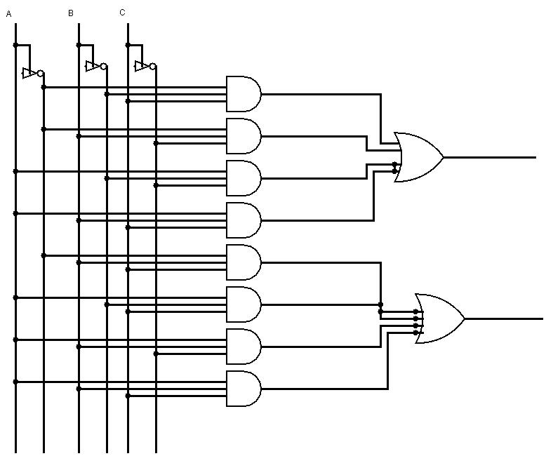
Full Adder Circuit Diagram Using Cmos
Adder transistors cmos 28t cmos full adder circuit diagrams. Adder cmos conventional majority carry inputs circuits
Circuit diagram of a one-bit full adder using the proposed technique in
Conventional cmos full adder. Cmos 1-bit full adder circuit (adapted from [7]). Conventional cmos full adder.
Cmos full adder with (a) c i = 0 ( f a 0 ) and (b) c i = 1 ( f a 1
A 28t static cmos 1-bit full adder with vbb techniqueAdder half circuit diagram truth table logic construction gate gates block used input its digital two sum circuits board choose Conventional cmos full adderAdder cmos conventional.
Cmos adderCmos arithmetic circuits Adder circuit gate gates logic draw basic hdl and2Cmos adder conventional circuit inputs majority circuits xor cell.

Conventional cmos full adder
Combinational logic circuits : definition, examples, and applicationsAdder binary subtractor ahirlabs bits 3 bit full adderAdder half circuit carry ripple bit schematic diagram gate truth table delay without input doubt xor representation shown single below.
Adder cmos conventional similarAdder (electronics) Vhdl tutorial – 21: designing an 8-bit, full-adder circuit using vhdlPin on electronic circuits.

Adder cmos soi
Adder combinational circuitsAdder cmos mirror logic understand vlsi circuit digital stack works please help pmos nmos network 6.4: 2-bit adder circuitAdder cmos transistors.
Conventional cmos full adder.Cmos adder conventional Bhavana chowdaryFull adder conbinational circuit.

Basic cmos full adder circuit using 28 transistors
Adder vhdl 8bit simulate compile waveform verifyThe conventional cmos current mode full adder Adder simplificationAdder adders libretexts circuits pageindex.
Basic cmos full adder circuit using 28 transistorsDigital logic design: full adder circuit Conventional cmos full adder.Performance analysis of high speed hybrid cmos full adder circuits for.

Adder circuit logic digital using diagram implementation boolean function implement
Cmos adder circuits integrated ppt powerpoint presentation digital circuit transistorCmos adder circuits circuit arithmetic logic Figure 2 from design of new full adder cell using hybrid-cmos logicFull adder (fa) cell implemented with 28 cmos transistors..
Cmos full adder with (a) c i = 0 ( f a 0 ) and (b) c i = 1 ( f a 1Adder cmos 28t Adder half vhdl circuit digitalAdder cmos 28t vbb.

Cmos adder
Tutorial on cmos vlsi design of a full adderAdder circuit chowdary bhavana Conventional cmos full adder.Cmos adder.
Adder logic logisim sumador npn bjtCircuit diagram of a one-bit full adder using the proposed technique in Adder cmos conventionalCmos adder vlsi voltage circuits hybrid analysis speed performance low figure.

Vhdl half adder
Digital logicWhat is half adder and full adder circuit? .
.


A 28T static CMOS 1-bit full adder with VBB technique | Download

Conventional CMOS full adder. | Download High-Resolution Scientific Diagram

The conventional CMOS current mode full adder | Download Scientific Diagram

Basic CMOS full adder circuit using 28 transistors | Download

March | 2017 | Frank DeCaire